Project HomeSpecificationsImagesAutomatic CalculatorCalculationsCAD FileAuthor

Blackbird Project
Project author: Noah TurnerLast modified: Sun 090416
Project designation: Blackbird v10
Project objective: Build a high-powered rocket capable of supersonic flight and an apogee of at least 1500 m, stabilized by an autonomous on-board control system, and able to withstand multiple flights and landings.
Delivery timeline: Design stage complete. Construction deadline originally August 2016, now postponed.
About the project
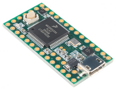
The Teensy 3.2 board employed in the rocket
The design is entirely original, and the build makes minimal use of prefabricated components. The body is to be constructed of carbon fiber reinforced polymer, which is a multi-layer carbon fiber wrap hardened with epoxy. The fins will contain the same material, but with a balsa core for rigidity and improved strength. Due to the difficulty of forming a tangent ogive shape from raw carbon fiber without professional tools, the nose cone is made of polypropylene. This type of plastic has an extremely low density at .86 grams per cubic centimeter, and a relatively high melting point of over 160 °C, well beyond the effects of aerodynamic heating even at speeds over Mach 1. These materials are meant to greatly increase the durability of the rocket over more typical cardboard or phenolic model rockets, while keeping the overall weight far below rockets of metal construction. The frame is intended for many flights over an indefinite period of time.
Current phase
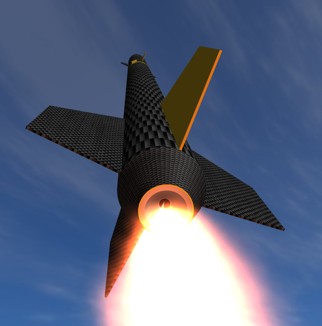
Rendering of the Blackbird in flight
At present, the project is in the design phase. By this point, every part of the rocket has been planned out in detail, but the design is not final. Once flight path calculations are complete, optimization of various physical parameters will take place in order to ensure that the objective is achieved by the final product. This must take place before the beginning of the second phase, which starts with material acquisition, and proceeds into the build itself. The vendors and the amounts of material needed are already known, but for obvious reasons, the design must be finalized before any part of the build is initiated.
The most important part of the building phase is the molding of the body tube and the cutting of fins. The nose cone and parachutes will be purchased, and the wood centering rings will be custom-made by a rocket parts supplier. All other internal and external parts, such as the exhaust cone, tail cone, motor mount, and camera housing, will be made from scratch. The second phase also includes connecting and soldering the circuitry for the control system, and programming the Arduino chip to respond correctly to environmental variables.
Next is the testing phase, which requires several launches of the rocket, followed by close analysis of its performance, based on the data it collects during its flight. Under consideration will be the achievement of the rocket's altitude and speed objectives as measured by the on-board pressure altimeter and timer, the stability of the flight as measured by the accelerometer and gyroscope, and its ease of recovery through the use of a dual-deployment system and GPS tracker. Any performance discrepancies in the tests will be subsequently fixed, and the rocket will be retested at another date.
The final phase of the project takes place in an office, and consists solely of documenting all the work done up to that point. Any persistent differences between the calculated predictions and the actual results will be analyzed, and their causes determined. At the conclusion of the last phase, a comprehensive report of the entire project will be written and published on this page.
Design challenges
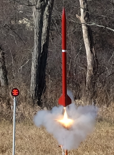
Another rocket by the same builder leaving the pad
Among the unsolved challenges are setting up a GPS transmitter to send the final location of the rocket to a mobile device, minimizing motor cost, and calculating center of pressure, center of gravity, stability, and coefficient of drag. The first is a matter of both hardware and software. The setup will need several modules in conjunction with each other, as well as an interface on the mobile device in question. The second problem has little room for solutions. Multiple launches are planned, each one using a single costly motor reload. The motor also needs a particular, reusable metal casing, which is almost as expensive. Briefly considered was the idea of building the motors from scratch, which was eventually dismissed being time- and cost-inefficient, as well as introducing several new variables. Local purchase, instead of the more typical Internet order, could at least remove the large hazardous material shipping fee. The final challenge is the most difficult, and involves complex mathematics, especially in regard to coefficient of drag, which requires further research.
Under consideration
A number of features have not yet been implemented in the design, but are being considered for the final product. One such feature is the ability to change parameters and download flight data from a mobile phone without the need to open the rocket. For example, whether the altitude cut-off is in effect for a particular flight, as well as the exact height or time at which it occurs, could be set at launch without the need to connect the system to a computer. Another potential addition to the rocket is a small LCD, mounted internally and visible through a plastic window on the side of the rocket, which could give height, velocity, and time readouts for easy post-flight viewing.